Quantcast
Channel: Raspberry Pi – Surveillance System, Security Cameras, and CCTV Equipment Articles & Videos

How to Send Push Notifications from Raspberry Pi

$
0
0

Send Push Notifications from Raspberry Pi

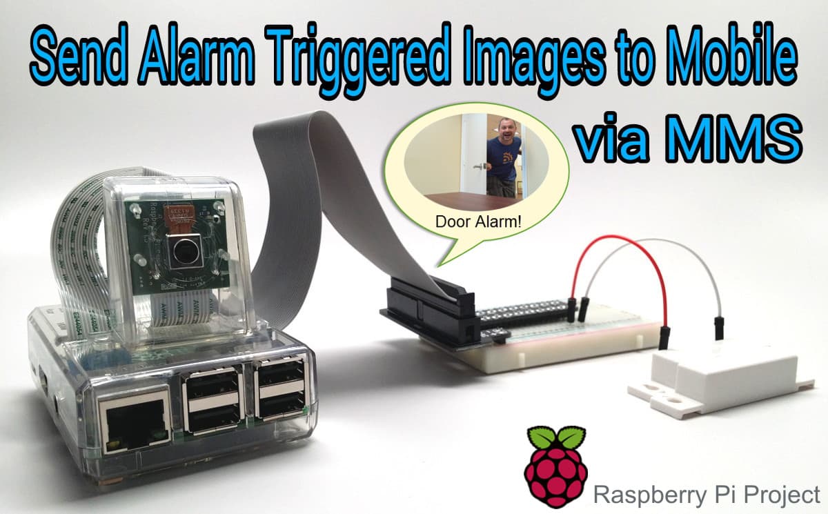
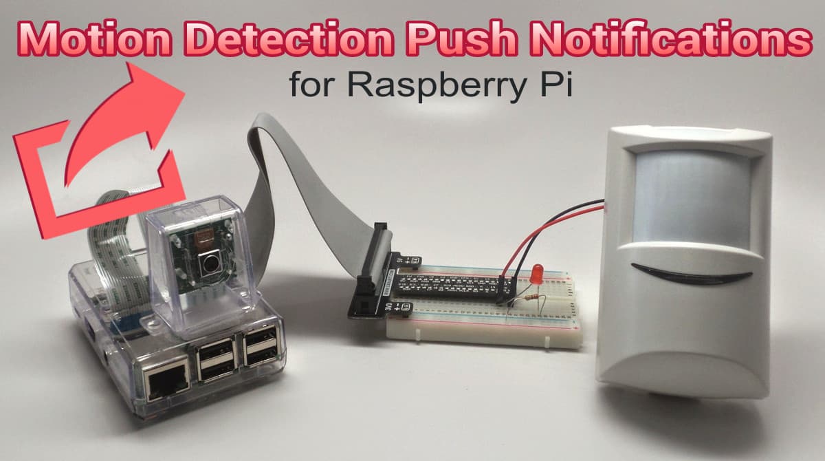
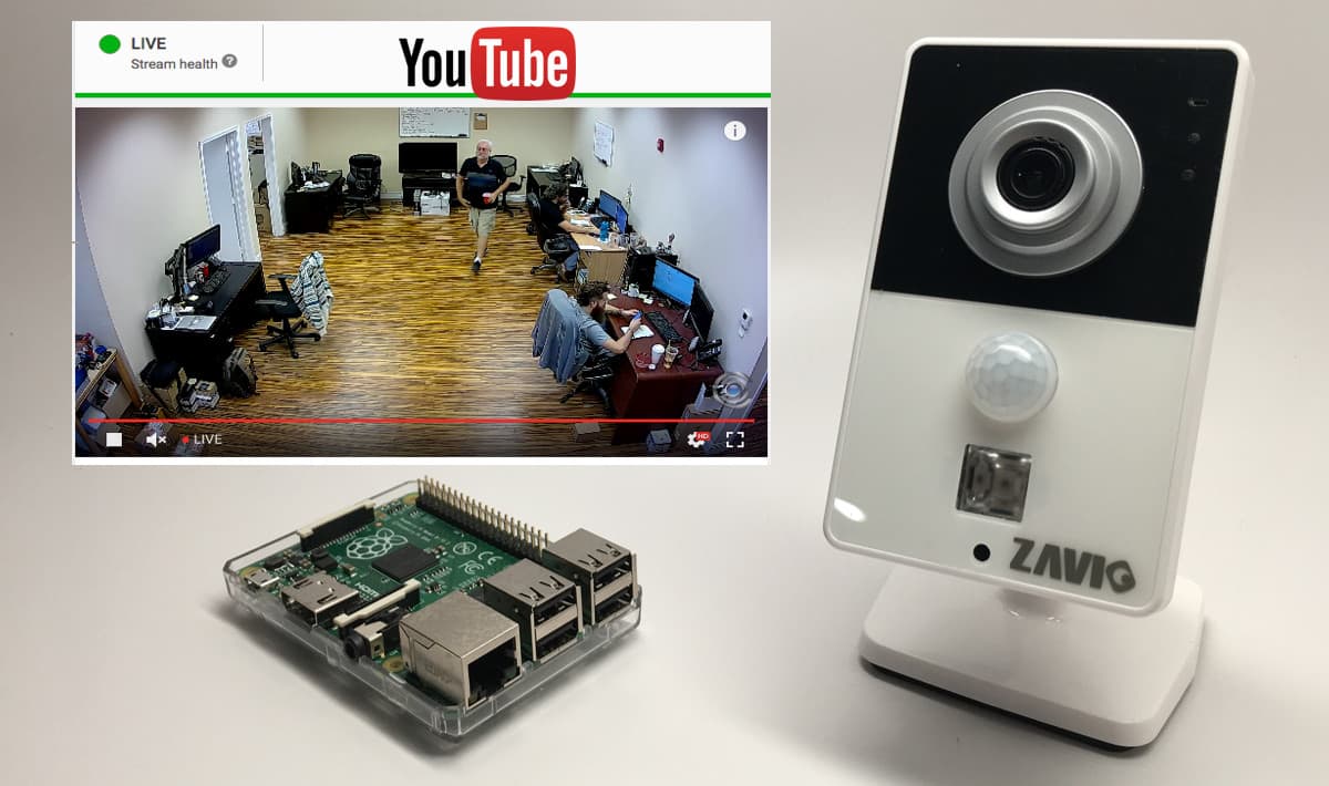
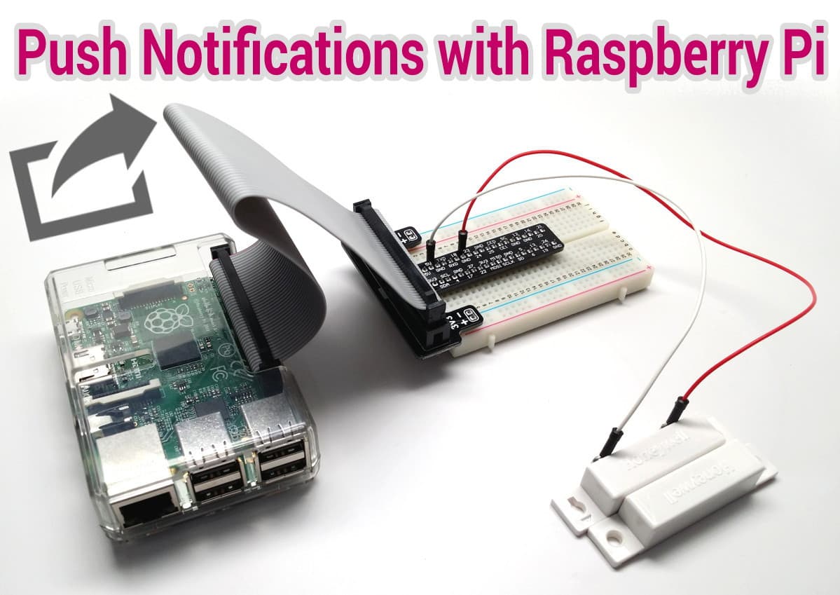
This project demonstrates how to send push notifications from Raspberry Pi to iOS and Android devices using a free push app. The idea is to trigger the event of sending the push message with a magnetic door sensor. When the door opens, the Raspberry Pi sends the message. The magnetic door sensor can easily be replaced in this project with some other type of alarm device such as a PIR motion sensor, infrared trip wire, or other. You can also setup your RPi to handle multiple sensors and push messages.

Disclosure: I am not a Python coding expert or an expert on Raspberry Pi (yet). Although, I have a lot of software engineering experience and I was once a full time developer, this is my very first Raspberry Pi project and Python application. My main motivation for this project was designing a solution that could work with the CCTV and HD security camera systems that my company supplies. Unfortunately, most CCTV DVRs do not yet support push notifications. So, I thought that an alarm input push notification server based on Raspberry Pi would provide an inexpensive solution to work in conjunction with these systems.

It is likely that the Python code is not the cleanest and there may be better ways to setup the Raspberry Pi. I am certainly open to constructive criticism and suggestions. Please post any comments at the bottom of this blog post if you have any.

 Setup Raspberry Pi to Send Push Messages

Here are the things that need to be done.

  1. Setup Push Service at Instapush & Install Mobile App
  2. Wire Door Sensor to Raspberry Pi
  3. Install pycurl library
  4. Install Python Code
  5. Run Python App
  6. Test and Get the Push Notification

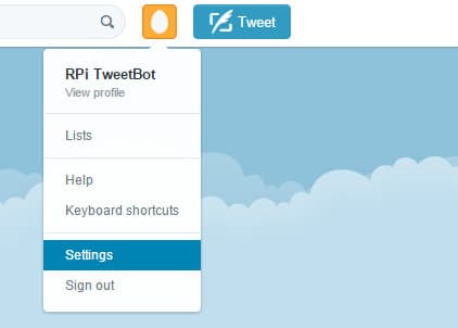
Setup Instapush Account & Install app

To handle the push notifications, I used a free push service called Instapush. Instapush has free apps for iOS and Android and the platform also has a simple to use REST API for software developers.

  1. Sign up for an account here: https://instapush.im/ and login.
  2. Download the apps here:
    iOS App
    Android App
  3. Login to the app(s) using the same login that you created on the website.
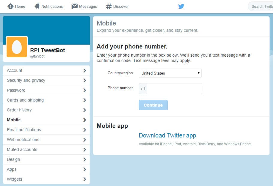
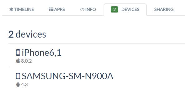
  4. After you login to to the mobile app on one or more devices, you will see your device linked to your Instapush account in the control panel. Go here: https://instapush.im/dashboard.
  5. Then click on the devices tab. I have two devices linked to me account. Here is what it looks like.
    mobile push devices
  6. Next, click on the apps tab, then Add Application.
  7. Choose a name for your application then click Add. I named my “Door Push”.
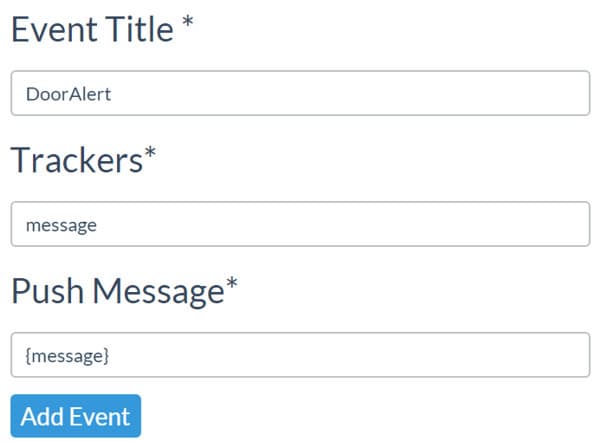
  8. After you add your application, you will brought to the events screen. Click Add Events.
  9. Choose a title for your event. I recommend not using any spaces in the event name. I used “DoorAlert”.
  10. You need to add at least one tracker. This is basically a variable that is used in the push notification. I used “message”.
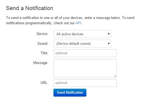
  11. Last, type what you want your push message to say. My Python code passes the {message} variable to the Instapush service so I recommend that you just add {message} to the Message field with nothing else.
    push notification API
  12. Click Add Event.
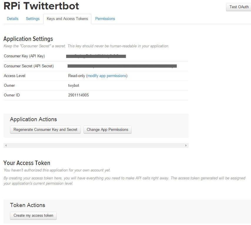
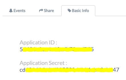
  13. Click on the Basic Info tab and make note of the Application ID and Application Secret fields. You will need these in the python code. You can see what this looks like below. I blocked out my ID and key.
    push service key

Wire Door Sensor to Raspberry Pi

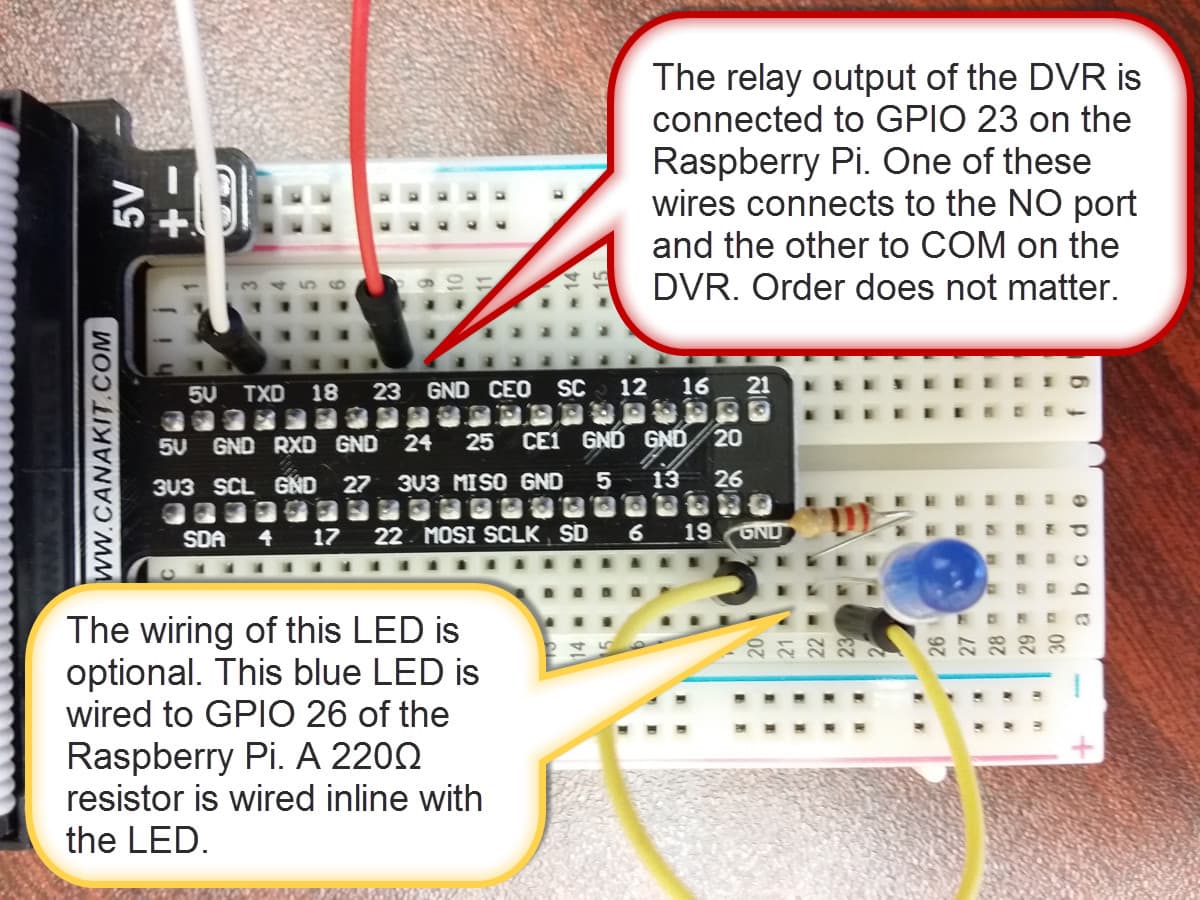
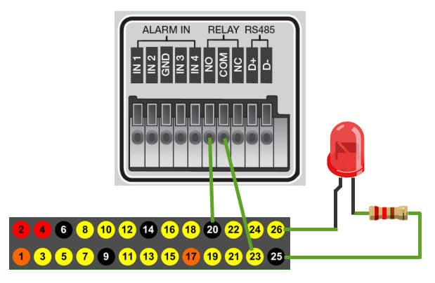
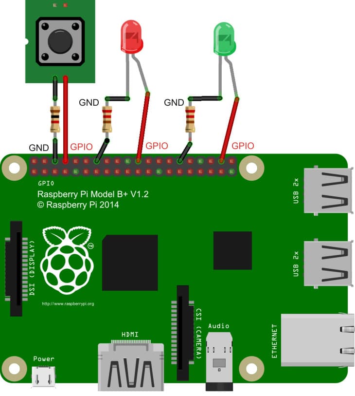
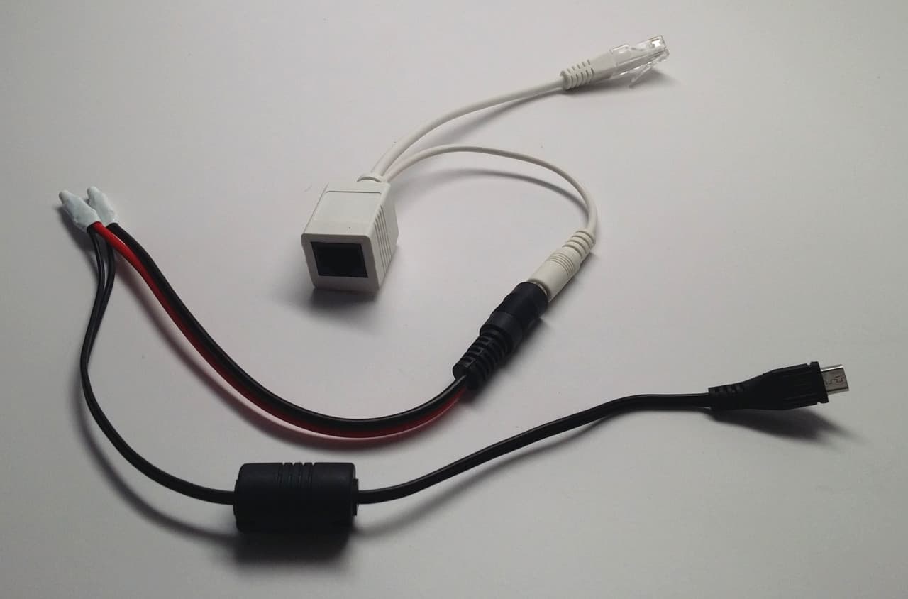
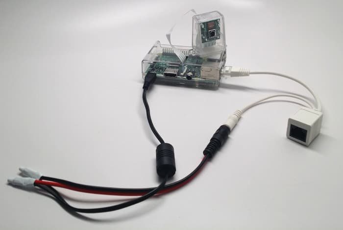
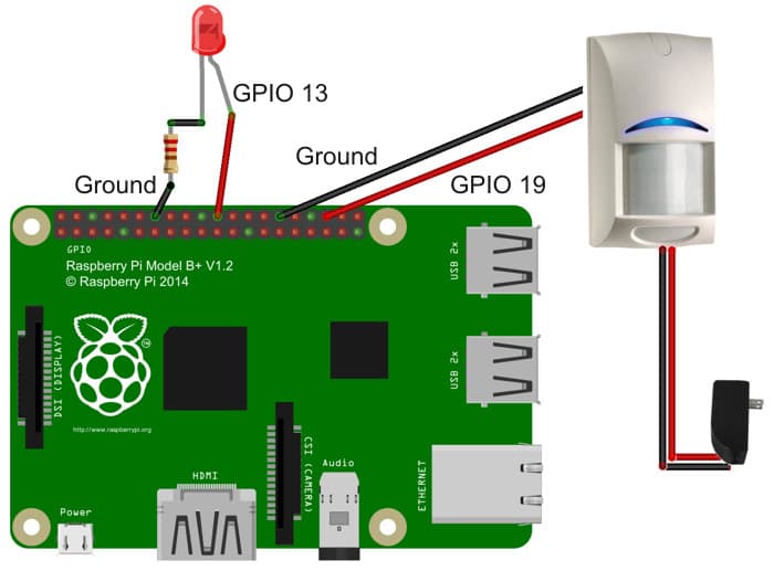
I am using a breadboard kit to make it easier to wire the door sensor to Pi. I use GPIO pin 23 and a ground pin to wire the door sensor. It does not matter which lead goes to the GPIO and which goes to the ground. Here is what the wiring looks like.

Raspberry Pi magnetic door sensor wiring


Install pycurl library

The python app will use a library called pycurl to send the API request to the Instapush server. Run the following command on your Raspberry Pi to install this Python library.

sudo apt-get install python-pycurl

Python Code

Here is the python application that I wrote. The comments in the code should explain pretty well what is going on. Name your program doorSensor.py. I am pretty sure that the formatting of the code will be messed up when I paste it into this blog post, so you can download the Python source here.

# ------------- Begin doorSensor.py ------------------ #

import pycurl, json
from StringIO import StringIO
import RPi.GPIO as GPIO


#setup GPIO using Broadcom SOC channel numbering
GPIO.setmode(GPIO.BCM)


# set to pull-up (normally closed position)
GPIO.setup(23, GPIO.IN, pull_up_down=GPIO.PUD_UP)


#setup InstaPush variables


# set this to Application ID from Instapush
appID = ""


# set this to the Application Secret from Instapush
appSecret = ""


# leave this set to DoorAlert unless you named your event something different in Instapush
pushEvent = "DoorAlert"


# set this to what you want the push message to say
pushMessage = "Door Opened!"


# use StringIO to capture the response from our push API call
buffer = StringIO()


# use Curl to post to the Instapush API
c = pycurl.Curl()


# set Instapush API URL
c.setopt(c.URL, 'https://api.instapush.im/v1/post')


# setup custom headers for authentication variables and content type
c.setopt(c.HTTPHEADER, ['x-instapush-appid: ' + appID,
'x-instapush-appsecret: ' + appSecret,
'Content-Type: application/json'])


# create a dictionary structure for the JSON data to post to Instapush
json_fields = {}


# setup JSON values
json_fields['event']=pushEvent
json_fields['trackers'] = {}
json_fields['trackers']['message']=pushMessage


postfields = json.dumps(json_fields)


# make sure to send the JSON with post
c.setopt(c.POSTFIELDS, postfields)


# set this so we can capture the resposne in our buffer
c.setopt(c.WRITEFUNCTION, buffer.write)


# uncomment to see the post that is sent
#c.setopt(c.VERBOSE, True)


# setup an indefinite loop that looks for the door to be opened / closed
while True:


# door open detected
GPIO.wait_for_edge(23, GPIO.RISING)
print("Door Opened!\n")


# in the door is opened, send the push request
c.perform()


# capture the response from the server
body= buffer.getvalue()


# print the response
print(body)


# reset the buffer
buffer.truncate(0)
buffer.seek(0)


# door closed detected
GPIO.wait_for_edge(23, GPIO.FALLING)
print("Door Closed!\n")


# cleanup
c.close()
GPIO.cleanup()


# -------------------- End doorSensor.py -------------------- #

Save the Python script on your Raspberry Pi.

Start Python App

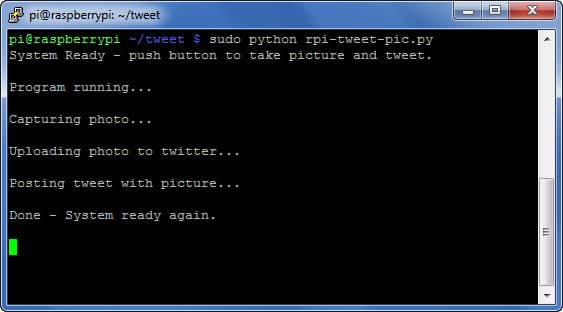
To test the push notification from Pi, run the doorSensor.py application. While the app is running. separate the magnetic door sensors from each other. You will see the following printed on the screen of your Raspberry Pi. The first line is the command to start the program. The second line is printed when we open the door. Immediately following is a printout of the response received from the push API service. Last, we print when the door is closed.

pi@raspberrypi ~ $ sudo python doorSensor.py

Door Opened!

{“msg”:”Notification Sent Successfully”,”error”:false,”status”:200}

Door Closed!

Get Push Notification

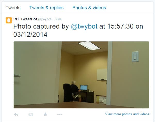
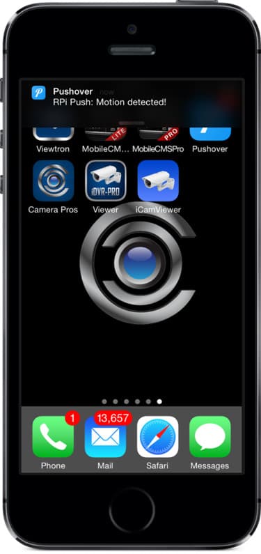
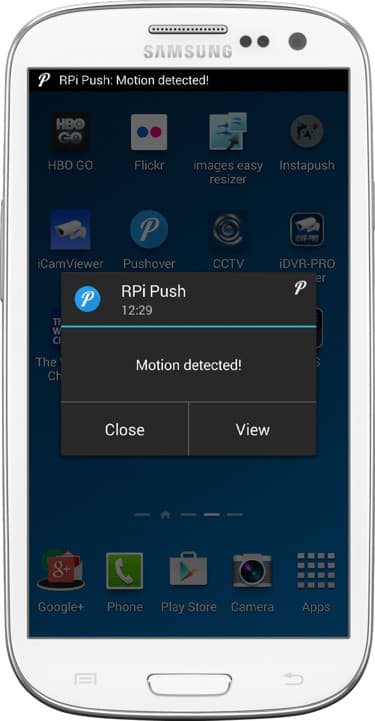
A second or two after you open the door sensor, you should receive the push notification on your iOS or Android app. Here is what the push message looks like when I received it on my Samsung Galaxy. It works just as awesome on my iPhone.

Raspberry Pi push message


Handling Multiple Alarm Sensors & Push Messages

I kept this project very simple by just integrating one alarm sensor with my Raspberry Pi. You may want to have multiple sensors in your project. Maybe you want to have more than one door sensors, PIR motion detectors, or virtually any other type of sensor that can be connected to RPi.

Obviously, you would want the push notification to tell you which sensor was triggered. This is very easy to handle.

By default, I have the pushMessage variable set using the below code.

pushMessage = “Door Opened!”

Simply add some logic to your code and modify the pushMessage variable based on which sensor triggered your alarm.

For example.

pushMessage = “Back Door Opened!”
pushMessage = “Motion detected at front door!”


CCTV DVR Push Notifications using Raspberry Pi

$
0
0

CCTV DVR Push Notifications using Raspberry Pi

This goal of this article is to document how to enable mobile push notifications on any CCTV DVR using Raspberry Pi. The problem that this project aims to solves is this: many surveillance DVRs that are currently installed around the world were manufactured before the invention of push notifications for iOS and Android mobile devices. In addition, there are still many CCTV manufacturers that have not yet developed push notifications even if they have mobile apps that enable access their DVRs. CCTV Camera Pros speaks to many customers around the world that want to enable push alerts, but do not want to replace their existing DVR. This can be done by adding a Raspberry Pi to your security system and using the source code that I will provide that integrates with a free push notification service from Instapush.

If you are going to attempt to use this project with your DVR, there is one prerequisite: your DVR MUST have an alarm relay output. Alarm in / alarm out ports are very typical even on older security DVRs. Look on the back of your DVR. If it has alarm inputs and outputs, they will  look something like this. The relay outputs can usually be identified with the labels NO / NC / COM, which stands for normally open, normally closed, and common.

CCTV DVR Alarm Relay Output

Unfortunately, if your DVR does not have these alarm output ports, you will not be able to enable push notifications using this Raspberry Pi project.

Setup DVR Alarm Output to Send Push Messages through Raspberry Pi

This project builds off of the “How to Send Push Notifications with Raspberry Pi” project that I published last week. Actually, the Python code that this project uses is almost identical to that one. I just replace the magnetic door sensor as the trigger for the push message with the alarm output of the DVR. I also added an LED output that turns on when the alarm is triggered, but that part is optional. Some of the steps below will reference that project because the setup is the same.

  1. Setup Push Service at Instapush & Install Mobile App
  2. Wire DVR Alarm Relay to Raspberry Pi
  3. Configure DVR Alarm Output
  4. Install Python Code
  5. Run Python Code
  6. Trigger DVR Alarm to Send Push Message

Wire DVR Alarm Relay Output to Raspberry Pi

Here is how my Raspberry Pi is wired for this project. Please note that the LED wired to GPIO 26 is optional. I included it so that I can easily see when the DVR alarm is on.  If you decide that you want to use an LED, you should connect a resistor in-line with the LED. I used a 220Ω resistor. The reduces the power that the LED receives and prolongs its life.

CCTV DVR to Raspberry Pi Wiring

Here is another view of how the alarm relay output and LED are wired to the Raspberry Pi.

Raspberry Pi Alarm Input Wiring

Configure DVR Alarm Relay Output

Different surveillance DVR models support different types of events that can trigger their alarm relay output(s). This part of the project setup is done on your DVR. The iDVR-PRO CCTV DVR supports the following types of alarms. Any of these can be used to trigger the push alert if you are using an iDVR-PRO.

  • Alarm Sensor – you can setup external alarm inputs to trigger an alarm relay output.
  • Video Motion Detection – motion detection from any camera.
  • Video Loss – video being lost on any camera.
  • Disk Drive Alert – disk drive system events such as disk full, failure, overwrite started.
  • Network Event – network events such as remote login failure, Internet connection failure, and DDNS update failure.
  • Panic Recording – initiation of panic recording.
  • System Event – system boot-up warning, login failure, fan failure.
  • Tamper Detection – DVR tampering detected.

So again, the type of event / alarm that you can use will depend on your DVR. This part of the project setup is completely independent of your Raspberry Pi. You should follow the instructions for setting up alarm output on your DVR. Here are the alarm setup instructions for the iDVR-PRO, which you may be able to use to improvise if your DVR does not have instructions.

Install Python Code

Here is the python application that I wrote. The comments in the code should explain pretty well what is going on. Name your program dvrPush.py. I am pretty sure that the formatting of the code will be messed up when I paste it into this blog post, so you can download the Python source here.

Be sure to enter your Instapush application ID and secret in those variable values in the code.

# ------------- Begin doorSensor.py ------------------ #
import pycurl, json
from StringIO import StringIO
import RPi.GPIO as GPIO

# LED Setup
ALARM_IN = 23
LED = 26 # removed this line if you do not setup the LED

#setup GPIO using Broadcom SOC channel numbering
GPIO.setmode(GPIO.BCM)

# set to pull-up (normally closed position)
GPIO.setup(ALARM_IN, GPIO.IN, pull_up_down=GPIO.PUD_UP)
GPIO.setup(LED, GPIO.OUT) # removed this line if you do not setup the LED
GPIO.output(LED, False) # removed this line if you do not setup the LED

#setup InstaPush variables
appID = “” # add Instapush application ID here
appSecret = “” # add Instapush application secret here
pushEvent = “DoorAlert”
pushMessage = “Door Opened!”

# use this to capture the response from our push API call
buffer = StringIO()

# use Curl to post to the Instapush API
c = pycurl.Curl()

# set API URL
c.setopt(c.URL, ‘https://api.instapush.im/v1/post’)

#setup custom headers for authentication variables and content type
c.setopt(c.HTTPHEADER, [‘x-instapush-appid: ‘ + appID,
‘x-instapush-appsecret: ‘ + appSecret,
‘Content-Type: application/json’])

# create a dict structure for the JSON data to post
json_fields = {}

# setup JSON values
json_fields[‘event’]=pushEvent
json_fields[‘trackers’] = {}
json_fields[‘trackers’][‘message’]=pushMessage
#print(json_fields)
postfields = json.dumps(json_fields)

# make sure to send the JSON with post
c.setopt(c.POSTFIELDS, postfields)

# set this so we can capture the resposne in our buffer
c.setopt(c.WRITEFUNCTION, buffer.write)

# uncomment to see the post sent
#c.setopt(c.VERBOSE, True)

# setup an indefinite loop that looks for the door to be opened / closed
while True:

# DVR Alarm received
GPIO.wait_for_edge(ALARM_IN, GPIO.RISING)
GPIO.output(LED, True) # removed this line if you do not setup the LED
print(“DVR Alarm Started!\n”)

# send the push request to Instapush
c.perform()

# capture the response from the Instapush server
body= buffer.getvalue()

# print the response from the Instapush API call
print(body)

# reset the response buffer
buffer.truncate(0)
buffer.seek(0)

# DVR alarm has stopped
GPIO.wait_for_edge(ALARM_IN, GPIO.FALLING)
GPIO.output(LED, False) # removed this line if you do not setup the LED
print(“DVR Alarm Ended.\n”)

# cleanup
c.close()
GPIO.cleanup()

# ——————– End doorSensor.py ——————– #

Save the Python script on your Raspberry Pi.

Run Python Code

To test the push notification, run the dvrPush.py application. While the app is running. Trigger the alarm output on your DVR. How you do this will depend on the type of event you configured on your DVR to trigger the relay. You will see the following printed on the screen of your Raspberry Pi when the alarm is sent from the DVR to Rpi. The first line is the command to start the program. The second line is printed when the DVR triggers the relay output. Immediately following is a printout of the response received from the push API service. Last, we print when the event on the DVR has ended and the relay is opened.

pi@raspberrypi ~ $ sudo python dvrPush.py

Door Opened!

{“msg”:”Notification Sent Successfully”,”error”:false,”status”:200}

Door Closed!

Send Push Notification

A second or two after you trigger the DVR alarm, you should receive the push notification on your iOS or Android app. Here is what the push message looks like on an Android Samsung Galaxy. It works just as awesome on iOS.

Raspberry Pi push message

Send Security Camera Photos from Raspberry Pi via MMS Text Message

$
0
0

Raspberry Pi Send Photo to Mobile via MMS Message

This project demonstrates how to setup Raspberry Pi as a security camera system that can take a photo snapshot send the image to mobile phones using MMS text messages. The action is triggered by an GPIO alarm input. I use a magnetic door sensor to trigger the alarm in the Python application that I wrote, but any type of sensor or event can be setup to trigger the Raspberry PI to take the snapshot and send the message. I use a service called Twilio to send the MMS text messages because they have a simple Python SDK for programmers and the service is free to use when in trial mode.

Setup Raspberry Security Camera System

Here are the things that need to be done to setup this project.

  1. Setup Twilio Account
  2. Install Apache Web Server
  3. Install Python Code
  4. Install Pi Camera & Wire Door Sensor
  5. Setup Static IP address
  6. Setup Port Forwarding
  7. Setup Dynamic DNS (optional)
  8. Run Code / Get MMS Message
  9. Run Alarm Code On Boot

Update 11/6/2014: Alternative use of imgur API instead of running a web server on Raspberry Pi

After launching this project, I received some great feedback on Reddit. /u/kurashu89 made a suggestion to use the imgur API instead of hosting the image on an Apache web server instance. Doing this has the following benefits.

  1. There is no need to setup a web server and use additional memory resources on RPi
  2. No need for the RPi to have a static LAN IP address
  3. No need for port forwarding
  4. No need to worry about DDNS

The one additional step that is required if you would like to use imgur for the snapshots is that you need to setup a imgur account and register a developer application. So, if you decide to use this method, you can skip steps 2, 5, 6, and 7 above and you need to install the alternative imgur source code provided here.

Setup Twilio Account

Twilio makes sending SMS / MMS messages simple by managing the connections with all of the different mobile providers for you. Software developers can use a simple Python API / SDK to request that a message be sent and the Twilio service takes care of the rest. To enable a trial account, Twilio requires two things. 1) You need to verify the phone number that you wish to send messages to and 2) the Twilio service prepends “Sent from a Twilio Trial account” to trial account messages. As far as I can tell, the service is free to use as long as you are sending 250 messages or less per month.

  1. Signup for a free Twilio account here.
  2. As part of the signup process, you need to verify a phone number. Use the cell phone number that you want to send messages to.
  3. After you verify your phone number, Twilio will assign you an account phone number to use that is in the same area code as the number you verified. This is the phone number that will be sending MMS messages on your behalf.
  4. Click get started, then Go to Your Account.
  5. When you login to your account, you will see an Account SID and Auth Token field at the top of the screen. Click on the lock icon in front of the Auth Token field to reveal the value. Make note of these two values. You will need them for the Python code shortly.
    MMS Message Account
  6. Just below these fields you should also see your Twilio phone number. You will need this also when you configure the RPi camera application.

Install Apache Web Server

You are probably wondering why you need to install the Apache web server on your Raspberry Pi for this project. Here is the answer: in order for the Twilio service to send a photo with MMS messages, it needs to get the photo from a URL on the Internet. The Twilio SDK will retrieve the photo taken by your Raspberry Pi camera via a URL served by the Apache web server running on your RPi.

  1. If you do not already have Apache running on your Raspberry Pi, click here to follow these instructions on the RaspberryPi.org website.
  2. The default installation of Apache makes /var/www/ the DocumentRoot which means that is where the web server looks for files to serve. My Python application assumes that you are using the default “/var/www” DocumentRoot, but if you are not that is OK, you will just need to modify the APACHE_DOC_ROOT variable in the code.

Install Python Code

Before you install the Python script, you must install the Twilio SDK on your Raspberry Pi. Download the Twilio Python SDK here. There are several ways that you can install it that are documented on that page.

Apache Method

Here is the Apache based Python application that I wrote to create the security camera system. The comments in the code should explain what is going on pretty well. You will only need to modify the CONSTANT variables that are defined at the top part of the app.

You can download the source code here.

Imgur Method

This is the version of the system that uses Imgur instead of Apache (I know, I should merge the two into one code base). I will likely so that later.

You can download the Imgur based source code here.

  1. Install the pyimgur.py library by running the following command:
    sudo pip install pyimgur
  2. Download the source code to your Raspberry Pi. If your RPi is already connected to the Internet, use the following command to get the source code.
    wget http://videos.cctvcamerapros.com/downloads/python/mms-alarm.py
  3. Edit the mms-alarm.py application using the editor of your choice on your Raspberry Pi.
  4. Change these variable values in the code.
  5. SENSOR: you can leave this value set to 19 if you are going to use GPIO 19, otherwise change as needed.
  6. DELAY: this is set to zero, but if you want a delay time between the alarm sensor being triggered and the camera taking a picture, change this to the number of seconds of delay that you require.
  7. ACCOUNT_SID: put the value from your Twilio account here.
  8. AUTH_TOKEN: put the value from your Twilio account here.
  9. TO_PHONE: this must be set to the phone number that you want your Raspberry Pi to send the MMS message to. This must be the phone number that you already verified during the Twilio account setup.
  10. FROM_PHONE: this must be set to the phone number that Twilio assigned to you during the account setup process.
  11. TXT_MSG: this is the text message that you want to be sent along with the photo that your RPi will take.
  12. CLIENT_ID: (ONLY for imgur code) this is the imgur Client ID assigned to the app you registered.
  13. HOSTNAME (not used if using imgur): set this to the public IP address (or the DDNS hostname) of your Raspberry Pi and the port number that you will use for forwarding. This WILL NOT work using a LAN IP address because the Twilio service will be accessing your Raspberry Pi from remotely over the Internet. IP addresses begining with 192. or 10. WILL NOT work. This is explained further in the port forwarding and DDNS sections of this project.
  14. APACHE_DOC_ROOT (not used if using imgur): if you installed your Apache web server with the default DocumentRoot, you do not need to change this value.
  15. IMG_DIR (ONLY for imgur code): location where you want the snapshot saved on your RPi.
  16. IMG: this is the name of the photo that will be saved. There is no need to change this unless you do not want the image to be named snap.jpg. This image will be overwritten each time the alarm is triggered.
  17. IMG_WIDTH: I have the image size set to 800 x 600 by default. I do not have any need to send a high resolution image over text, but if you do, you can change it here.
  18. IMG_HEIGHT: see explanation above.
  19. Save the file after you have changed these values.

Install Camera & Door Sensor

I am not going to document how to install a Raspberry Pi camera in this project because there are plenty of articles and videos available online that can show you how to do that. Just search Google for “install raspberry pi camera” if you have not yet installed yours.

The door sensor wiring is very simple. You can use any magnetic door sensor. I am using a Honeywell. Wire one of the terminals of the sensor to GPIO pin 19 of your Raspberry Pi or any other GPIO of your choice. The mms-alarm.py code that I provide is setup for GPIO 19, so if you use a different pin, make sure you update the SENSOR variable. Wire the other sensor terminal to a ground (GND) port of your Pi. you can see my wiring below. I am using a breadboard which is totally overkill for such a simple project, but I still like using it.

wire raspberry pi door sensor

Setup Static LAN IP Address (DHCP Reservation)

If you want to save a lot of time and frustration, you should set a static LAN IP address for your Raspberry Pi. I recommend doing this by reserving an IP address in your router. I find this method to be most reliable and most routers have an IP reservation function. The process to do this will depend on your specific router type. Here are instructions for a D-Link router. The concepts are the same for any make and model of router but the interface will be different. Do a search online for your specific model. Search for “LinkSys IP reservation” or “Linksys DHCP reservation”. Obviously replace Linksys with your manufacturer and model.

Setup Port Forwarding

When the Python application calls the Twilio MMS service, one of the parameters that is passed to Twilio is the URL on your Raspberry Pi where the image to send with the message is located. Because the Twilio service will be accessing this URL from remotely over the Internet, it is necessary to setup port forwarding to the Apache web server running on your RPi.
Just like the DHCP reservation setup above, the concept of port forwarding is the same but the setup process is different depending on your specific router.

By default, Apache web servers run on port 80. Please watch the below video if you want to understand port forwarding better. In concept, replace the IP camera used in the video with your Raspberry Pi and the computer on the left of the network diagram in the video with the Twilio service and you should understand how port forwarding will be working for this project.

You can find port forwarding instructions here for many popular manufacturers. Do a Google search for your specific make and model if you can not find yours there.

Dynamic DNS Setup (DDNS)

If the Internet connection where your Raspberry Pi is located does not have a static IP address, you should setup a Dynamic DNS account (DDNS). You can find an explanation of DDNS and setup instructions for some routers here. If you do end up setting up DDNS, then be sure to use your DDNS hostname in the HOSTNAME variable of the mms-alarm.py application. If your internet connection uses a static IP, then it is not necessary to setup DDNS and you can simply use the IP address of your Internet gateway in the HOSTNAME variable.

If you need to find your Internet IP address and if you would like to test to make sure that you have port forwarding setup correctly, please use this online port forward checker tool. The tool also displays your Internet IP address.

Run Alarm Code / Get MMS Message

You can test the project by starting the Python application manually. After you confirm that it works correctly, you may want to automatically startup the Python application when your Raspberry Pi boots up.

To start the app manually, change directory to where it is located and type the following command:
sudo python mms-alarm.py

When your door is opened (alarm sensor separated), the following will be printed on the screen: Door Opened!

Within a few seconds, you will receive the MMS message with the photo attached that your Pi camera captured. Mine looks like this.

Raspberry Pi Send MMS Message with Photo

Startup Alarm Application on Boot

If you decide to use this project in real life, you will most likely want the alarm code to startup when your Raspberry Pi boots up. To start the program on boot, you can add a startup command to the rc.local file on you RPi. This file will either be located in /etc or /etc/rc.d

Change directory to /etc to see if your rc.local is located there. If it is not, change directory to /etc/rc.d.

Edit the rc.local file using the text editor of your choice and add the following line before the last line in that file which should read “exit 0″
python /home/pi/alarm.py &

Save the file, then reboot your Raspberry Pi and test the alarm application again by opening your door.

That is all. If you have any questions, you can email me at mike@cctvcamerapros.net.


Raspberry Pi Twitter Project: Push Button, Camera Capture, Tweet Photo

$
0
0

Raspberry Pi Twitter

In this project, I program my Raspberry Pi (using Python) to take a picture using a Pi camera, then share the photo via Twitter when a button is pressed. I use the Twython python library to integrate with the Twitter API. I realize that I am not the first person to document a Twitter project like this, but I chose to share my own version for a few reasons.

1) I kept getting the following warning from the Twython library when using the update_status_with_media() method.
“TwythonDeprecationWarning: This method is deprecated. You should use Twython.upload_media instead.”

All of the projects that I found online used that deprecated method to tweet a photo. After a bit of research, I found the new method of photo sharing via the Twitter API requires that you make two API calls. One to upload the media file and the second to tweet using the reference the ID of the media file. The Python code for this project gets rid of that warning.

2) I really like to use the GPIO ports on Raspberry Pi when I can.  I have been designing and developing software for many years but I am still a noob when it comes to electrical circuitry design. So, I wanted to use a push button to trigger the tweet and use LEDs to report the status of the process. Not the most intricate of wiring projects, but every bit of experience helps.

3) I tested this entire process on a brand new install of the Raspbian os for Raspberry Pi. I wanted to provide step by step instructions using a fresh install so that I can document any library dependency that I may run into.

Project Setup Steps

Follow these steps to configure and program your Raspberry Pi to take a photo and share it via Twitter when you push a button.

  1. Add Mobile Number to Twitter
  2. Setup Twitter App
  3. Install Pi Camera
  4. Install Python Libraries
  5. Install Program Code
  6. Wire Raspberry Pi
  7. Run the Code / Press the Button

Add Mobile Phone Number to Twitter

To interface with the Twitter API / SDK, you must setup a Twitter app that has both read and write access to your timeline. In order to do this, you must have a Twitter account with a verified mobile phone number associated with it. After you create the app, you can remove your mobile number. I assume that you already have a Twitter account, but if you do not, please create on here.

  1. Login to your Twitter account.
  2. Click on your Twitter icon in the upper left and select Settings.
    twitter raspberry pi project
  3. After you are logged in, click on the Mobile link on the left.
    twitter python phone number
  4. Add your mobile phone number and click Continue.
  5. A verification code will be send to you. Enter that code on the confirmation screen.

Setup Twitter App

  1. From the same web browser where you are logged  into your twitter account, go to https://apps.twitter.com/
  2. Click on Create New App.
  3. Fill in Name, Description, and Website. Agree to T&Cs. Click Create your Twitter application button. Do not worry if you don’t have a website for the project, just fill this in with any valid web address. Be sure to include the “http://”.
    twitter raspberry pi python project
  4. Click on Permissions Tab. Select Read and Write. Press Update settings.
    raspberry pi twitter setup
  5. Click on the Keys and Access Tokens tab, then click on the Create my access token button.
    twitter app setup keys
  6. After you press the Create my access token button, you will see the Access Token and Access Token Secret fields. Keep all of these field values handy. You will need them for the Python code.
    Consumer Key (API Key)
    Consumer Secret (API Secret)
    Access Token
    Access Token Secret

Install Pi Camera

If you do not already have a Pi camera connected to your Raspberry Pi board and enabled, please follow the instructions here to get that done. If you prefer to use a USB web cam, you can find instructions to set that up here. If you are a noob, I recommend using a native Pi camera because my project code is already setup to use one.

Install Python Libraries

Use the below commands to install the required Python libraries. The only one required for this project is twython.

In case you do not already have pip installed, I included commands to install that first. Remember, I am testing this from a fresh Raspbian build. If you already use pip to install Python libraries, you can skip steps 1 and 2.

  1. sudo apt-get update
  2. sudo apt-get install python-pip
  3. sudo pip install twython

Install Program Code

Here is the source code for the project. The comments explain what is going on.

You can download the source code here if you do not want to use wget to retrieve it.

  1. I recommend creating a new directory for any project. You can use this command to create a new directory.
    mkdir tweet
  2. Change into that directory using this command.
    cd tweet
  3. You can use the following command on your Raspberry Pi to retrieve the source code for this project. It will be placed in the tweet directory as long you are there when you run it.
    wget http://videos.cctvcamerapros.com/downloads/python/rpi-tweet-pic.py
  4. Edit the rpi-tweet-pic.py using your favorite text editor. I use vi.
  5. Look for the variables: apiKey, apiSecret, accessToken, and accessTokenSecret and enter the values from the Twitter app that you created.
  6. By default, I have the image size set to 1280 x 720. You can adjust this by editting the IMG_WIDTH and IMG_HEIGHT variables.

Wire Raspberry Pi

Here is how I wired the push button and LEDs to my Raspberry Pi board. Pushing the button is the action that initiates the camera taking a photo, then uploading and sharing the photo via Twitter. The green LED is used to indicate that the system is ready and you can press the button. The red LED indicates that the program is running. I am using resistors with the LEDs and button.

Disclosure: Though I aspire to be one day, I am not an electronics expert at this time. I am much stronger at software system design and development. If you see anything wrong with the way I have wired my board, that will not surprise me.  If you have any suggestions for improvement, please let me know. I used resistor sizes that I saw being used in other projects using similar hardware.

Also please note that the image below does not reflect the actual GPIO ports that I used in my project code. I use these ports on the diagram because they were spaced out to make it easier to see. You can use any three GPIO ports that  you choose, but please note that if you do not use the ones that I did, you need to modify the following variables in the code.

BUTTON = 12
SYSTEM_READY = 26 # indicates that program is ready to be run
SYSTEM_RUNNING = 13 # indicates that program is running
Raspberry Pi Twitter Project Wiring

Run the Code / Press the Button

It’s time to start the program and push the button to test it out. Here is a terminal session that shows how to do that.

Rasperry Pi Send Tweet

  1. Run this command:
    sudo python rpi-tweet-pic.py
  2. The program will start. When it is ready, the following message will appear and the green LED light will turn on.
    System Ready- push button to take picture and tweet.
  3. When you push the button, the green LED light turns off and the red one turns on which indicates that the program is running.
  4. The program prints out a status at each stage.
  5. When it is complete the following message is displayed, the red LED turns off and the green LED turns back on.
    Done – System ready again.

This is what it looks like on Twitter.

Raspberry Pi Tweet Picture


Not the most exciting tweet. That is the view from my office. My Raspberry Pi and camera are sitting on my desk. That is my brother out there hard at work.

How to setup a Raspberry Pi Video Streaming Server in 5 Minutes

$
0
0

Raspberry Pi Video Streaming

Here is a super easy way to setup video streaming on Raspberry Pi so that you can access live video from iOS, Android, Windows, and Mac. This project basically turns your Raspberry pi camera into a live webcam. The best part is that it actually takes less than 5 minutes to setup.

I have been developing and testing a lot of Raspberry Pi projects lately, especially ones that use the pi camera. I really love having complete control over this tiny Linux computer to do things like create time lapse video, auto sharing photos on twitter, and send push notifications based on alarm events.

My latest project craving was to setup live video on a web page that I could access from the web browser on my iPhone. A quick search on Google revealed many existing projects that already did this. So, I read through some of the more recent ones to try and pick the best one.

One of the articles that I came across was Miguel Grinberg’s Video Streaming with Flask. Miguel’s explanation on his blog was very thorough and his code looked very clean. I was also interested in learning more about Flask (which his app used). So I used these simple steps that I documented here to install Flask, setup a MJPEG server, and access the live video stream from my phone.

To my delight, I was able to get a live video streaming server running on my Raspberry Pi in under 5 minutes by using the project that Miguel shared on Github.

This is what it looked like from iOS when I was done.

Raspberry Pi Video Streaming

Here is how it is setup. If you do not already have a Pi camera setup, please refer to this page to do that first. By the way, I am using the Raspbian operating system on my RPi.


Raspberry Pi Streaming Video Setup

  1. If you do not already have pip installed on your Raspberry Pi, please use this command to install it:
    sudo apt-get install python-pip
  2. Install the picamera library by running this command:
    pip install picamera
  3. Install the flask Python library by running this command:
    sudo pip install flask
  4. Download Miguel’s Flask video streaming project by running this command:
    git clone https://github.com/miguelgrinberg/flask-video-streaming.git
  5.  In the project folder edit the app.py file.
    Comment out this line by adding a “#” to the beginning
    #from camera import CameraUn-comment this line
    from camera_pi import Camera
  6. Save the file.
  7. Run this command to find out the local IP address of your Raspberry Pi.
    ifconfig
  8. You will see many lines of output. You are looking for this one:
    inet addr:192.168.0.107 Bcast:192.168.0.255 Mask:255.255.255.0
  9. The inet addr is your local IP address. In this case, 192.168.0.107.
  10.  Start the Flask server by running this command:
    python app.py
  11. You will see this, which means that the server is running on port 5000 and is ready.
    * Running on http://0.0.0.0:5000/
    * Restarting with reloader
  12. Open up a web browser on your favorite device and go to this address http://192.168.0.107:5000, except replace that IP address with the one that your Raspberry Pi is running on.
  13. You should see a live view the video that your Raspberry Pi is capturing.

I hope that this project got you up and running as quickly as it did for me. Please note that I did not get into how to setup port forwarding so that you could access your camera remotely over the Internet. These instructions will only work from a computer that is connected to the same local area network as your Raspberry Pi. You can refer to these notes and instructions from another project if you want to configure your Raspberry Pi for remote access.


How to Enable Power Over Ethernet on Raspberry Pi

$
0
0

Raspberry Pi Power Over Ethernet

You can enable Power over Ethernet for Raspberry Pi by using a passive PoE injector / splitter system. They are very easy to setup and they are very inexpensive. They cost about $7-$10 for a pair (injecter / splitter).

I have been working on a social camera project on my Raspberry Pi for a while now. Very soon, I will be mounting my Raspberry Pi in an outdoor housing to the back of my house. You can see pictures of the camera housing that I am using here. My back yard has a nice view of a lake where there are always lots of birds, turtles, butterflies, and occasionally an alligator.

The place where I will mount the Raspberry Pi and camera is a spot where I previously had an IP camera mounted, so there is already a CAT5 cable run to that location that connects the router inside my house. The IP camera that was previously mounted used PoE, so I did not also run 18/2 power cable and there are no power outlets located anywhere close-by.

Passive Power Over Ethernet to the Rescue

Did you know that you can use a passive PoE injector / splitter system to enable power over Ethernet to non-PoE low voltage network devices?

Raspberry Pi  PoE Injector / Splitter

Here’s how you can setup PoE for Raspberry Pi

  1. Cut the cable on your mini USB Raspberry Pi power supply. Be sure to leave the ferrite bead on the side with the min-USB plug (as seen below).
  2. Attach one side of the cut cable to a PT-3 power cable lead. It does not matter which side. I used some crimp on wire connectors (as you can see below), but you can use twist-ons, solder, or any method that you prefer to attach the power cable to the PT-3 power lead. The other side will be attached to a PT-4 power lead because one side of the injector / splitter system has a male 2.1mm power plug and the other has a female. But again, it does not matter which side you use for the power supply and which is used for the mini-USB connector.
    PoE SplitterHere is what the PoE splitter looks like when connected to the Raspberry Pi.PoE Splitter Raspberry Pi
  3. Attach the other side of the cut Raspberry Pi power supply cable to a PT-4 power lead, then connect to the injector / splitter.  Here is what mine looks like. Again, I used crimp on wire connectors.PoE injectorThis PoE injector side will eventually get connected to a network router or switch as you see below. Obviously, the power supply will get plugged in to a power source.PoE switch PoE injector Raspberry Pi

Network Diagram

Raspberry Pi Power over Ethernet wiring

Here is a network diagram that shows all of the pieces working together. I think that it looks more complicated than it really is.

This passive PoE system enables you to run a single CAT5 cable to your Raspberry Pi to provide both power and network connectivity. You can run the CAT5 up to about 130 feet depending on how much current your Raspberry Pi is drawing and the type of cable that you use.


How to Send Raspberry Pi Push Notifications Triggered by PIR Motion Detector

$
0
0

Raspberry Pi PIR Motion Detection Push Notifications

Here is a simple Raspberry Pi project that uses a PIR motion sensor from a burglar alarm to trigger a mobile push notifications to iOS or Android apps. Last year, I published a RPi project that used a magnetic door sensor and a push message service called Instapush. In this project, I use a PIR motion detector and a mobile push service called Pushover. I have been wanting to try Pushover and I ended up liking it better than Instapush because it is more reliable in my testing. I also like that it also has an email to push interface that is very handy for integrating network devices that have email sending capability.

Here are a few things I want to note upfront about this project.

  1. I am using a standard 12V DC alarm system motion sensor that is made for alarm systems, not a Raspberry Pi PIR sensor. The reason that I chose this one was because I am mounting the PIR sensor at my office and alarm system PIR sensors come in housings that are easy to mount. As much as I want to justify buying a 3D printer to print my own electronics cases, I am not quite there yet. I also wanted to show that it is safe to use the dry contacts of a 12V DC device with Raspberry Pi because no electrical current is flows through dry contacts. The circuit is simply closed or grounded when there is no motion and the ground is broken or opened when motion is detected.
  2. The PIR sensor is powered by a separate 12V DC power supply. The RPi will NOT power it.
  3. Although the above picture of my Raspberry Pi includes a camera, I did not use the camera for this project. It is a pain to remove it from the enclosure and the picture looks nicer with it there rather than an empty Velcro pad. However, this project can easily be enhanced to use the camera. You can get some ideas to integrate camera functions into this project from this MMS project and this streaming video project.

Project Setup Steps

  1. Create a Pushover account and download iOS or Android Apps
  2. Register Pushover Application
  3. Install Python Source Code on your Raspberry Pi
  4. Wire the PIR Motion Detector and LED to Raspberry Pi Board
  5. Run and Test Code
  6. Get Push Notifications on iOS and Android

Setup Pushover API and Download Mobile Apps

In this project, I chose to use the Pushover service to send push notifications. Pushover has an easy to use REST API and very nice apps for iOS and Android that are free to download. The REST API makes it simple for developers to use httplib and urllib Python libraries to interface with it.

The push service is free to use for 7 days then has a one time setup fee of $3.99 per platform. So, if you use both iOS and Android, it will cost you $3.99 x 2. If you have multiple iOS or Android devices, you only have to pay once per platform and can install on as many devices as you like.

  1. Sign up for a Pushover account here: https://pushover.net/
  2. Download the Pushover app for iOS and/or Android here.
    Download iOS App
    Download Android App
  3. Launch the mobile app and login using the user ID and password you selected when you signed up.
  4. When your device asks for permission for Pushover to send you push notifications, say yes.
  5. Login to your account from a desktop computer. https://pushover.net/
  6. From the Pushover control panel, send a test push message to make sure that the service and app are working. Below is a screenshot of the form that you can use to send the notification.
    send push notification
  7. In the Pushover control panel, you will see “Your User Key”. You will need this to use the Pushover API.

Register Pushover Application

Like most cloud based SDK / APIs, Pushover requires that you register your application. The process is simple.

  1. From the Pushover control panel, click on the Register an Application link.
  2. Create a name for your app. I named mine “RPi Push”.
  3. Choose “Application” from the type dropdown.
  4. Fill in a description.
  5. Check that you accept the terms and conditions, if you do, and press Create Application.
  6. After you successfully create your app, you will see a API Token/Key displayed. You will need this value, along with the Your User Key to use the API.

Install Program Code

Here is the Python source code for the project. The comments should explain clearly what is going on.


You can download the source code here.

From your Raspberry Pi, you can use the following command to retrieve the file:

wget http://videos.cctvcamerapros.com/downloads/python/pir.py

After you have installed the Python code on your Raspberry Pi, you need to edit following lines of the program.

# Pushover API setup
PUSH_TOKEN = "" # API Token/Key
PUSH_USER = "" # Your User Key
PUSH_MSG = "Motion detected!" # Push Message you want sent

Set the PUSH_TOKEN and PUSH_USER variables to the values assigned when you setup your Pushover account and application. If you want the push notifications to say something other than “Motion detected!”, you can change that value as well.

Wire PIR Sensor to Raspberry Pi

I used GPIO 19 for the PIR sensor and GPIO 13 for the status LED. If you choose to use different GPIO ports, be sure to update the pir.py application to reflect your GPIO ports. Please note that the below image does not accurately represent the locations on GPIO 13 and 19 on the Raspberry Pi. Please be sure to check the numbering of your Raspberry Pi or the breadboard that you are using to match up the GPIO ports that you use.

Also note that I used a 12V DC PIR sensor that is typically used in burglar alarms. I am powering the PIR sensor with it’s own 12V DC power supply. The Raspberry Pi is powered separately using a 5V power supply made for it.

wire PIR motion sensor to Raspberry Pi

Run and Test

With the Python code in place and the motion detector wired to your Raspberry Pi, you are ready to test.

  1. Make sure your Raspberry Pi and PIR sensor are both powered on.
  2. Start the program running the following command:
    sudo python pir.py
  3. Wave your hand in front of the motion detector so that it detects movement.
  4. You should see the value defined in the PUSH_MSG variable printed on the screen of your Raspberry Pi and shortly after you should receive a push notification.

iPhone Push Notification

iPhone motion detection push notification

This is what the push notification looks like on my iPhone.

Android Push Notification

Android motion detection push notification

This is what the push notification looks on my Android Samsung Galaxy.

Summary & Enhancement Ideas

I hope that you found this project easy to setup and useful. I tried to keep it as simple as possible. It is meant to be a starting point that can be expanded to do much more. Some ideas on how this project can be enhanced.

  • Integrate with a Raspberry Pi camera so that you can visually see what triggered the event.
  • Make it so that you can setup a schedule for when the alarm is active.
  • Enable output devices to take some type of action when motion is detected, like fire a Nerf gun or activate an alarm siren.
  • I use the alarm based Raspberry Pi projects that I design in conjunction with video surveillance systems.

Raspberry Pi IP Camera YouTube Live Video Streaming Server

$
0
0

YouTube Live Stream Video Raspberry Pi IP Camera

Read this article to learn how-to use a network IP camera and Raspberry Pi as a YouTube livestream video server.

Project Background

Several customers at CCTV Camera Pros contacted me recently asking if it was possible to use a Zavio IP camera for YouTube live streaming. RTSP is the video streaming protocol built into most network IP cameras, including Zavio. After some quick research, I found that RTSP (Real Time Streaming Protocol) is not directly supported by YouTube. YouTube uses RTMP (RTMP Real-Time Messaging Protocol).

After some additional research, I found examples of how FFmpeg can be used to re-encode an RTSP stream to RTMP. FFmpeg is a free software project that produces libraries and programs for handling multimedia data. It is the base platform for most major video streaming applications. FFmpeg can be compiled and run on just about any operating system – including Mac, Windows, and Linux.

FFmpeg on Mac

I performed my initial testing by installing FFmpeg on a Macbook Air laptop. I used the Zavio F4215 HD IP camera that we have mounted to the ceiling of the sales room at CCTV Camera Pros office. The test worked very well but I did not want to use my Macbook long term. I wanted to create a live streaming application that could run for many consecutive days, weeks, and even months – without needing any maintenance or attention from me. So, I could not use the laptop that I take to and from work.

FFmpeg on Raspberry Pi

Next, I decided to test the application with a Raspberry Pi. I purchased the latest Raspberry Pi 3. Before my test, I wondered if it had enough processing power and memory to handle the intense video encoding / decoding that FFmpeg would be performing continuously. I also had concerns regarding the continuous network communication required to take the RTSP stream from my IP camera on the LAN and send a 1080p HD resolution RTMP output stream to YouTube over the Internet.

So far, the Raspberry Pi is working very well. It has been running for a 4 days continuously (at the time of this writing — 11/16/2016). You can see the YouTube live stream embedded below. Click on the play button on the YouTube. It takes 5-10 seconds to begin buffering.


It is a live view of the sales room at CCTV Camera Pros. Sorry that it is not the most exciting view. I am just using this as a proof of concept for customers. Customers contact CCTV Camera Pros for solutions for how to live stream wildlife, beaches, mountains, and other much more exciting views than this. If the stream is down, please contact me at mike@cctvcamerapros.net. I intend to leave it up for a while.


Project Setup

If you want to setup a Raspberry Pi and IP camera to be a livestream video server for YouTube, follow these setup instructions.

IP Camera

Before you begin configuring a Raspberry Pi, you should first make sure that you have an IP camera that makes available a URL to directly access an RTSP stream. All Zavio IP cameras provide this. If you are using another brand, please check your IP camera’s technical documentation or ask the manufacturer to provide the RTSP stream and port that your camera model uses.

Here are the steps that I used to setup my IP camera.

  1. Make sure that you are connecting your IP camera to the same network as your Raspberry Pi. A hard wired connection will almost alwayts work better that wireless.
  2. You should configure a static LAN IP address for your IP camera. I normally do this on my router. If you do not know how to do this, search for your router model and IP reservation. Example google search: “Linksys router IP reservation”. That should point you in the right direction.
  3. Make note of the LAN IP address of your IP camera. It will be something like 192.168.0.100.
  4. Consult the manual for your IP camera to get the port number and URL that is used for its RTSP video stream. For Zavio IP cameras, you will use something like this.

    rtsp://192.168.0.100:554/video.pro1

    In this example, my IP camera’s IP address is 192.168.0.119. The RTSP port is 554 and the URL is /video.pro1.

Setup YouTube LiveStream

If you do not already have a YouTube channel / account, you need to register one first. Once you have a YouTube channel, follow the below instructions to configure your live stream.

  1. Login to YouTube dashboard by going here. https://www.youtube.com/dashboard?o=U
  2. Click on the Live Streaming > Stream now link on the left hand side menu.
  3. On the Stream Now page, scroll down towards the bottom of the page to find the Encoder Setup section. You need the Server URL and Stream name/key values to configure the BASH script that will be used to start and monitor the FFmpeg process on your Raspberry Pi. Your stream URL will look something like this: rtmp://a.rtmp.youtube.com/live2
    Your stream key will look something like this: d5gz-5d1p-143w-qbha

Raspberry Pi Setup

  1. I started with a fresh Raspbian operating system installation using NOOBS. You can learn how to do this step-by-step here.
    https://www.raspberrypi.org/documentation/installation/noobs.md
  2. After installing Raspbian, boot the Raspberry Pi and open a terminal window. Note: before you turn your Raspberry Pi on, connect it to a network with Internet access using the wired Ethernet port. This should be the same network that your IP camera is on.
  3. The next few steps will run from the terminal window.
  4. Run this command to install some libraries that are needed for the installation.
    sudo apt-get install git autoconf automake build-essential checkinstall libass-dev libgpac-dev libmp3lame-dev libopencore-amrnb-dev libopencore-amrwb-dev librtmp-dev libspeex-dev libtheora-dev libtool libvorbis-dev pkg-config texi2html zlib1g-dev yasm
  5. X264 is a library needed by FFmpeg. Run this command to install the X264 libraries on Raspberry Pi.
    cd /usr/src
    sudo git clone git://git.videolan.org/x264
    cd x264
    sudo ./configure –host=arm-unknown-linux-gnueabi –enable-static –disable-opencl
    sudo make
    sudo make install
  6. FDK-AAC is another video library that FFmpeg needs to use. Just like the X264 libs, you should install FDK-AAC before compiling FFmpeg. Run these commands to install FDK-AAC on Raspberry Pi
    cd /usr/src
    sudo git clone –depth 1 git://github.com/mstorsjo/fdk-aac.git
    cd fdk-aac
    sudo autoreconf -fiv
    sudo ./configure –disable-shared
    sudo makesudo make install
  7. Last, run these commands to compile and install FFmpeg on Raspbrery Pi. NOTE! This will take a long time (up to 3 or 4 hours) so be patient!
    cd /usr/src
    sudo git clone https://github.com/FFmpeg/FFmpeg.git
    cd ffmpeg
    sudo ./configure –enable-gpl –enable-libx264 –enable-gpl –enable-libass –enable-libfdk-aac –enable-libmp3lame –enable-libopencore-amrnb –enable-libopencore-amrwb –enable-libspeex –enable-librtmp –enable-libtheora –enable-libvorbis –enable-nonfree –enable-version3 –enable-nonfree
    sudo make
    sudo make install

BASH Process Monitoring Script

In my testing, I found that the FFmpeg process would stop from time to time for unknown reasons. To compensate for this, I wrote a simple BASH script that checks to make sure FFmpeg is running, and if it is not, it will restart it. It is a very simple process monitoring script.

Here is the BASH script.

  1. You can download the source code for the BASH script here.
  2. Put the BASH script in the /home/pi directory on your Raspberry Pi. Name it start.sh
  3. Edit the script and replace the values for these variables.
    RTSP_URL – replace this with the URL that your IP camera uses. If you are using a Zavio IP camera, this value does not need to change.
    YOUTUBE_URL – most likely this does not need to change, but confirm it in your YouTube dashboard.
    YOUTUBE_KEY – this is almost like a password so protect it wisely. You must change this value. The above key is not real.
  4. After you edit the script, save it and set the permissions of it to be executable. You can use this command: chmod 755 start.sh
  5. You can test the script by running it with this command: sudo ./start.sh
  6. When you run this command, you should see live video on the stream now page in your YouTube dashboard.

This is what the video stream looks like in the YouTube dashboard.

YouTube Livestream IP Camera

Setup Cron Job

Cron is a time based job scheduler for Unix and Linux systems. I configured a cron job to run the start.sh script every minute. The script checks to make sure the FFmpeg process is running. and if it is not, it restarts it. If FFmpeg is already running, the script does not do anything.

To setup the cron job on your Raspberry Pi.

  1. Run this command.
    crontab -e
  2. This will open the cron configuration file for user “pi”. Add the following line to the file.
    * * * * * sudo /home/pi/start3.sh
  3. Then save the file and exit the editor you are using.
  4. Cron is now configured and the start.sh script will run every minute.

Even if your Raspberry Pi reboots, the cron will run and automatically start the FFmpeg video encoding process.


Live Video Stream Embed in Mobile Apps

After setting up my livestream, I also embedded the video in CCTV Camera Pros mobile apps for iPhone and Android. This is the great thing about using YouTube. It enables you to embed the live video on just about any platform and you don’t have to worry about usage. Here is a screen shot of what the video embed looks like in the iPhone app.

YouTube Livestream Video Embed iPhone App

If you want to see the stream for yourself in the apps, you can download them here.

After you open the app, tap on the Videos section, then Live IP Camera Stream.


If you find any errors or ways to improve this project, please email me at mike@cctvcamerapros.net.